INERTRA™
Architecture
Loss of clamp load is seldom a single-event failure. It develops through micro-movement, relaxation, and rotational migration, reducing joint integrity long before failure thresholds are reached.
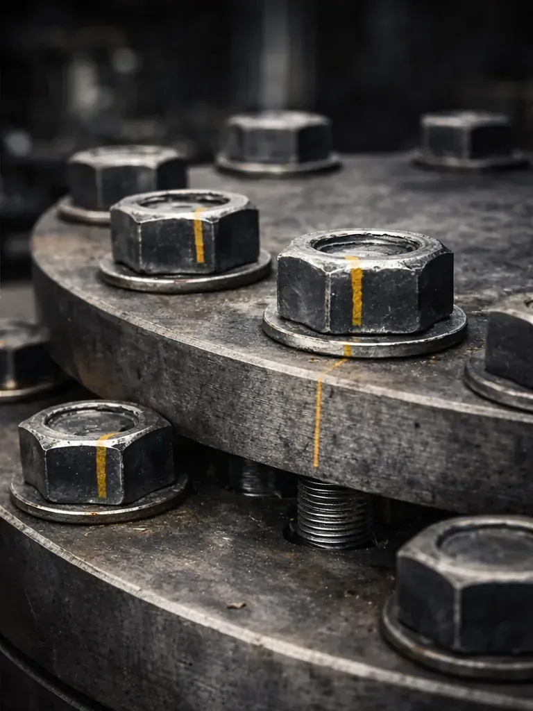
INERTRA™ is a patent-protected mechanical architecture framework engineered to preserve rotational constraint and disturbance stability in assemblies subject to sustained mechanical stress. Protected by issued U.S. patents. Additional technical references are provided under appropriate confidentiality.
Constraint-Based
Retention.
Conventional bolted joints rely on friction and preload. Under transverse vibration, repeated slip at the threads lets the nut back off and clamp load decays (Junker, SAE 690055, 1969). INERTRA™ Retention replaces friction dependence with a mechanical interlock: a nut and an opposite-hand bolt lock against each other, so the turn that would loosen one tightens the other.
Embedded Rotational Constraint
Constraint geometry is integrated directly within the fastener assembly: the stud, nut, and opposite-hand bolt lock against each other. The architecture mechanically limits micro-rotation as part of the structural load path itself.
No Adhesives Required
No chemical compounds, no lock-washers, no adhesives. Retention is mechanical and repeatable across service cycles, without cure variability or surface preparation sensitivity.
Designed for Long Duty Cycles
Intended for assemblies where retorque windows are infrequent, access is constrained, or downtime is costly. Performance in any application is confirmed through the licensee's own validation.
Controlled Disengagement
The architecture supports controlled removal and reinstallation, unlike adhesive-based approaches that can complicate field maintenance procedures.
The same principle applies to biomechanical environments such as orthopedic fixation and implant interfaces, where cyclic loading and micro-motion matter. Specific constraint geometry, claim mapping, integration drawings, and validation data are provided to qualified counterparties under executed NDA.
Why This Matters
Beyond the Interface
Interface-Level Root Cause
Duty cycle, vibration profile, load variability, access constraints, and packaging geometry determine whether an interface problem remains tolerable or becomes a recurring reliability issue that drives inspection and maintenance schedules.
Program-Level Cost Variable
What appears to be a localized fastening issue can compound into service intervals, field performance variability, inspection burden, warranty exposure, and broader lifecycle cost, all traceable to a single interface architecture decision.
Architecture Access for
Qualified Partners
Architecture access for qualified counterparties evaluating integration fit, shared within a controlled diligence path.
Operational Cost Context
Published unplanned downtime benchmarks (all causes, not fastener-specific): oil & gas almost $500K per hour (Siemens, 2022); typical industrial outage close to $125K per hour (ABB, 2023); about $59M per year for a large heavy-industry plant (Siemens, 2024). Sources.